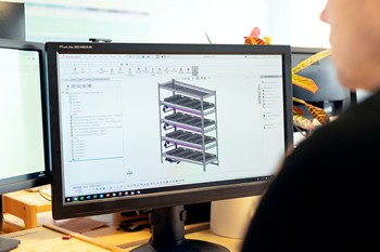
Learning Engineering drawings may seem like a daunting task, but in actual fact most Engineering drawings comply to very much the same principles.
Before diving in and starting to create Engineering drawings, some foundational principles needs to be understood.
Engineering Drawings are often referred to as Mechanical-, Technical- or manufacturing drawings.
A good rule to remember is that the person drafting or creating the drawing is the link between the inventor / designer and the manufacturer. All the information on the drawing should be clear and precises and nothing should be left for interpretation. Eg. A person machining a part on a lathe does not necessarily have the background of codes and specifications as stipulated by the person designing the part, and this also works the other way around.
If a drawing will be used to manufacture an equipment or part, clear instructions need to be given. In order to effectively create a Engineering drawing, it is necessary to understand what the drawing will be used for.
Here are some guidelines as to what information needs to be indicated on a Engineering drawing or set of drawings (to name a few):
Border or Format (as it relates to the drawing)
Every drawing needs to have a border with certain information and a title block. Some information may be the scale, unit of measurement (mm or inch), design house information and contact detail, the owner of the drawing, etc.
Drawing number
Drawing numbers are allocated to a drawing that gives the designer, manufacturer and end user of the equipment / part traceability of the specified equipment or part. These numbers may be allocated by the designer, but most often the end user will prescribe the number that should be indicated on the drawing(s). Each Drawing will have a unique number so that no duplicates can be made. This number will then be recorded in a drawing index.
Revision number and revision control
Revision control is extremely important in Engineering Drawings. Every time something is changes on a drawing, a new revision of the drawing needs to be created. This gives traceability to the drawing and ensures that manufacturers have the most up-to-date version of the drawing. If revision control is not implemented, it might happen that a drawing could have multiple different versions but it is not clear which one is the most current.
Designer
The designer of the equipment / part normally carries responsibility of the correctness of the design. Apart from the design house that needs to be indicated, the specific person doing the design also needs to be referenced.
General Arrangement
A General Arrangement (GA) of the equipment or part needs to be indicated on the drawing. In the case of drawings that was made for maintenance purposes, the part / modification / repair should preferably be show in position where it will be used. This is to give an overview of what needs to be done (or what has been done)
Notes
Notes on a Engineering Drawing are for information and instructions on What- and How- the work needs to be carried out. Often a designer would have specific steps that must be taken in the repair or manufacturing of a equipment / part.
Design Conditions
Design conditions on a drawing tells the manufacturer / inspection authority / end user what is the conditions the equipment or part was designed for. Not only does it show design conditions, it also gives information on the Design Code, Test pressures, Non Destructive Examination (NDE’s), service, etc.
Specifications
Some End users have specific specifications that must be taken into account when designing equipment or parts. These specifications needs to be listed on the drawing as to reference to the specific specifications that was used in the deigning and manufacturing process
A Bill of Materials (also called an Item List)
The bill of materials gives specific quantities, sizes and materials of components that must be acquired by the manufacturer to manufacture the equipment / part
Welding Symbols
Where welding is required, weld symbols or weld details should be indicated as instruction of the type and size of weld. Any post machining / grinding can also be indicated.
Dimensions
The sizes and dimensions of components needs to be indicated on details and assemblies as to give information to the manufacturer where components needs to be welded, machined or drilled.
Special notes
Special notes can refer to chamfers, bends, threaded holes, threaded bars, special instructions when getting to a certain point during manufacturing.
Machining instructions and surface finishes
Machining instructions gives the manufacturer a guideline of the roughness, tolerances and type of machining that is required by the designer. This is critical as there could be sealing faces that needs a smooth surface where others may require a rougher surface.
Tolerances
Tolerances are indicated in different ways on a Engineering Drawing. These tolerances will be prescribed by the CODE (ASME/API/etc) and should be indicated on the drawing. Not only is there tolerances in dimensions, but geometrical tolerances also needs to be adhered to.
Projection methods on Engineering Drawings
It is very important to indicate on the drawing if the projections are made using First or Third angled Projection system. This can vastly influence the interpretation of a 2D detail and if the wrong system is assumed, the equipment or part may be manufactured completely wrong.
In closing, this is not all the information noted on Engineering Drawings, but it gives a broad overview. Some information will be dictated by the type of drawing and the intended of the drawing itself.


