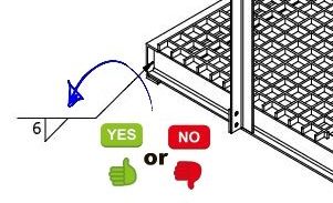
I have seen on a few forums that some people ask: “Is placing weld symbols on isometric views allowed?” and the answer is YES … only if the position of the weld is clear and there can be no other interpretation of how the weld should be done.
When placing weld symbols on isometric views, remember the following:
- The weld symbol should not over a part or assembly, always lave the weld symbol net, above or below the view
- Keep the symbol uncluttered where it can be easily visible
- The leader of the symbol should be a short as possible to keep the information centralized
- Do not refer to hidden details or joints with a weld symbol
- The text of a weld symbol should be the same size as the other text on the drawing
Below is an example of how I would placing weld symbols on an isometric view

The Arrangement is quite large, so it will not be very clear where weld symbols point to. I would rather enlarge certain details as sown above
Detail

These welds are clear to the manufacturer. The (TYP) in the tail of the weld refers to the other clips that also needs to be welded, thus it is Typical for all other clips.

For Enlarged Detail ‘B’, the welds on the hand rails are also typical, but as a alternative way, I noted below the heading of the detail that it is typical. The (TYP) can thus be omitted in the tail.

In Enlarged Detail ‘C’, I would only indicate the specific weld as shown. To show a weld on the top side of the weld symbol line (other side) would refer to the weld on the bottom of the plate, but in this case it will be ambiguous. I will rather not show a symbol in this case, so this detail can actually be deleted.

As marked with arrow ‘X’ on the Arrangement, I did not add a weld symbol to the Arrangement, because there is not a clear place where a weld symbol will be places. Instead, I made an extra Enlarged Detail ‘G’ to clearly show the position of the weld.
There are no rules prohibiting anyone to place weld symbols on isometric views.

